> ## Documentation Index
> Fetch the complete documentation index at: https://docs.omi.me/llms.txt
> Use this file to discover all available pages before exploring further.
# Building the Device
> Step-by-step guide to assemble your own Omi device from parts.
## Before You Start
Make sure you have all required components
Download and print the case STL files
If you don't have access to a 3D printer, check [Makerspace.com](https://makerspace.com/) for printing locations near you, or use an online 3D printing service.
***
## Assembly Instructions
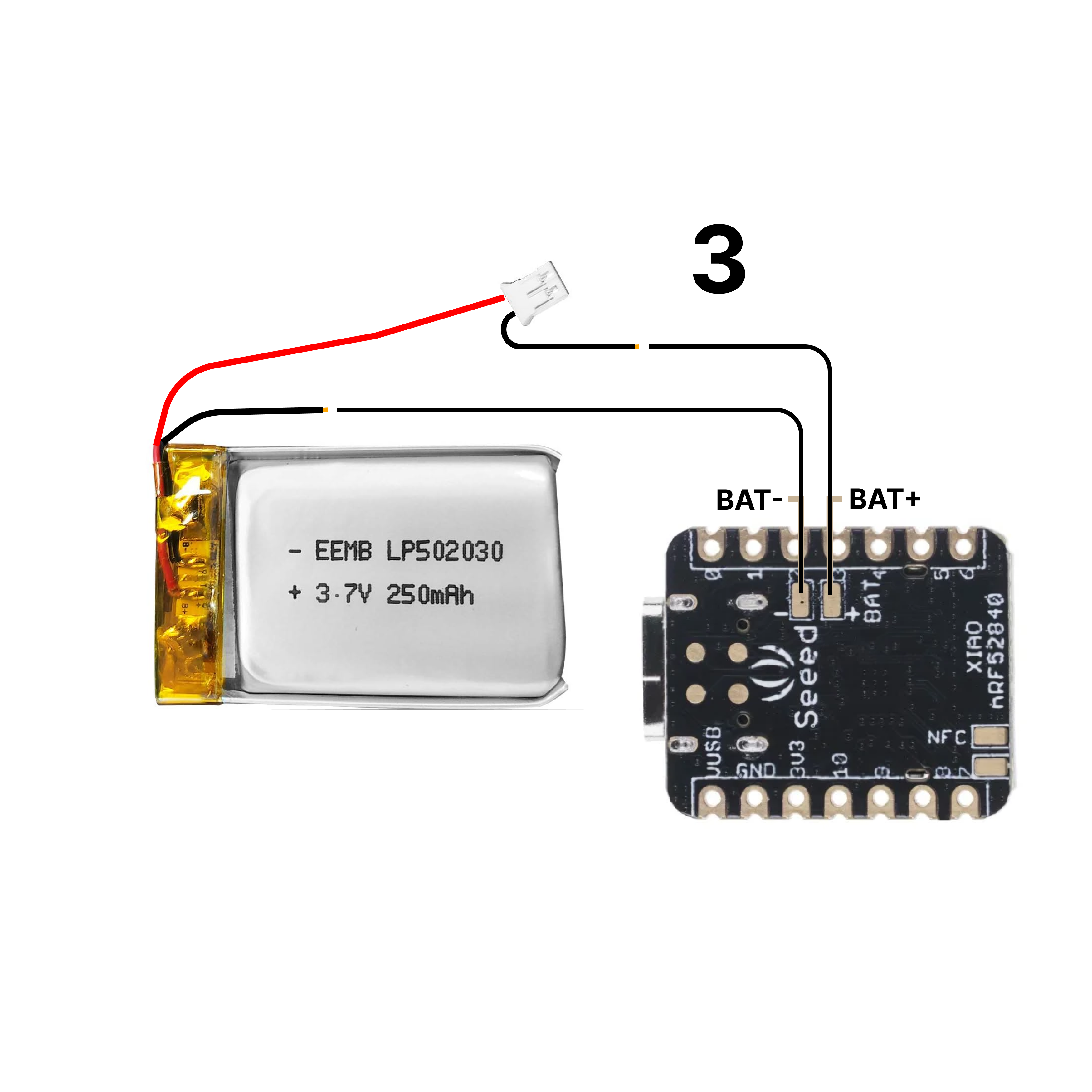
Gather all your parts: XIAO board, battery, switch, wires, and 3D printed case.
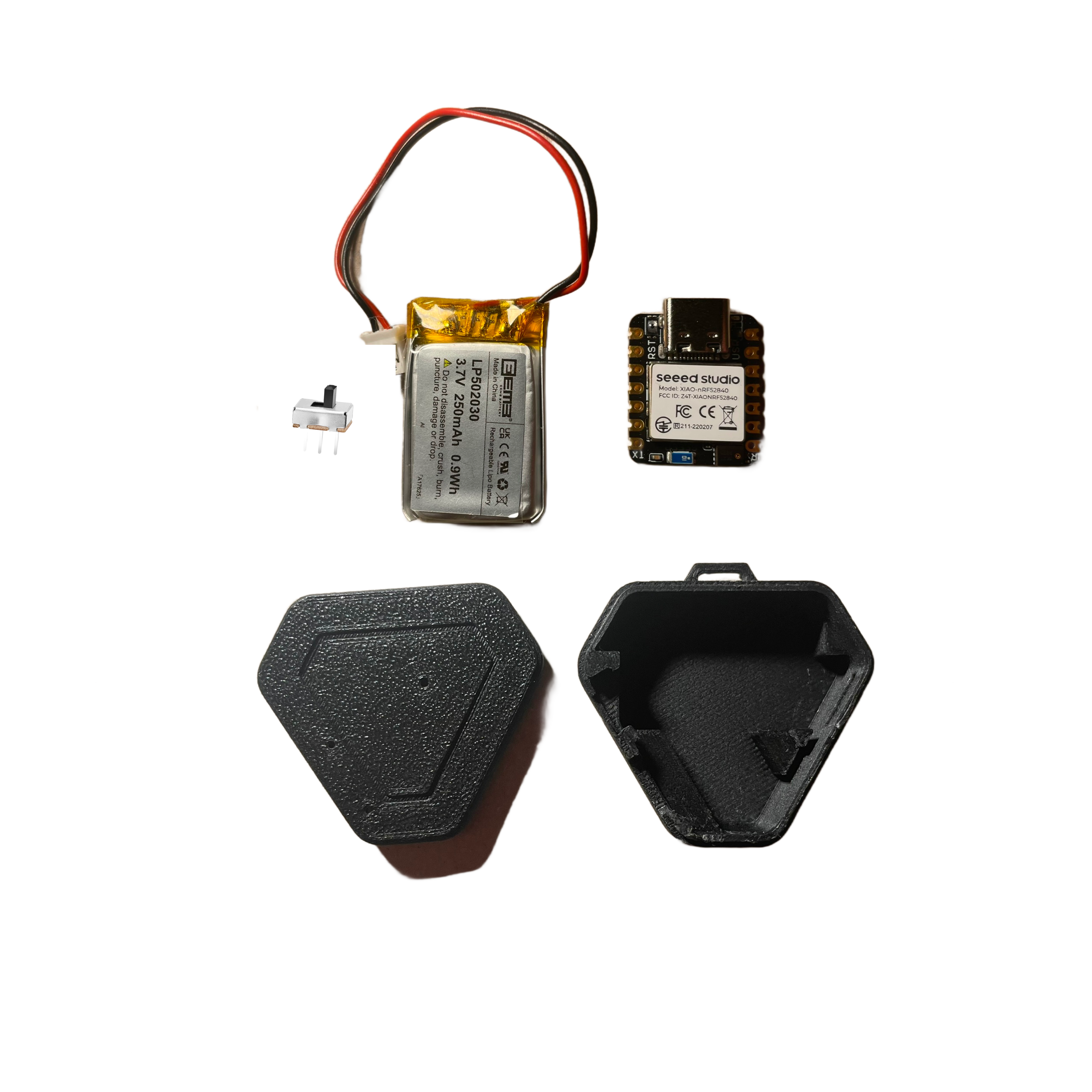 Cut the black wire approximately **2/3 inch (17mm)** from the base of the battery connector.
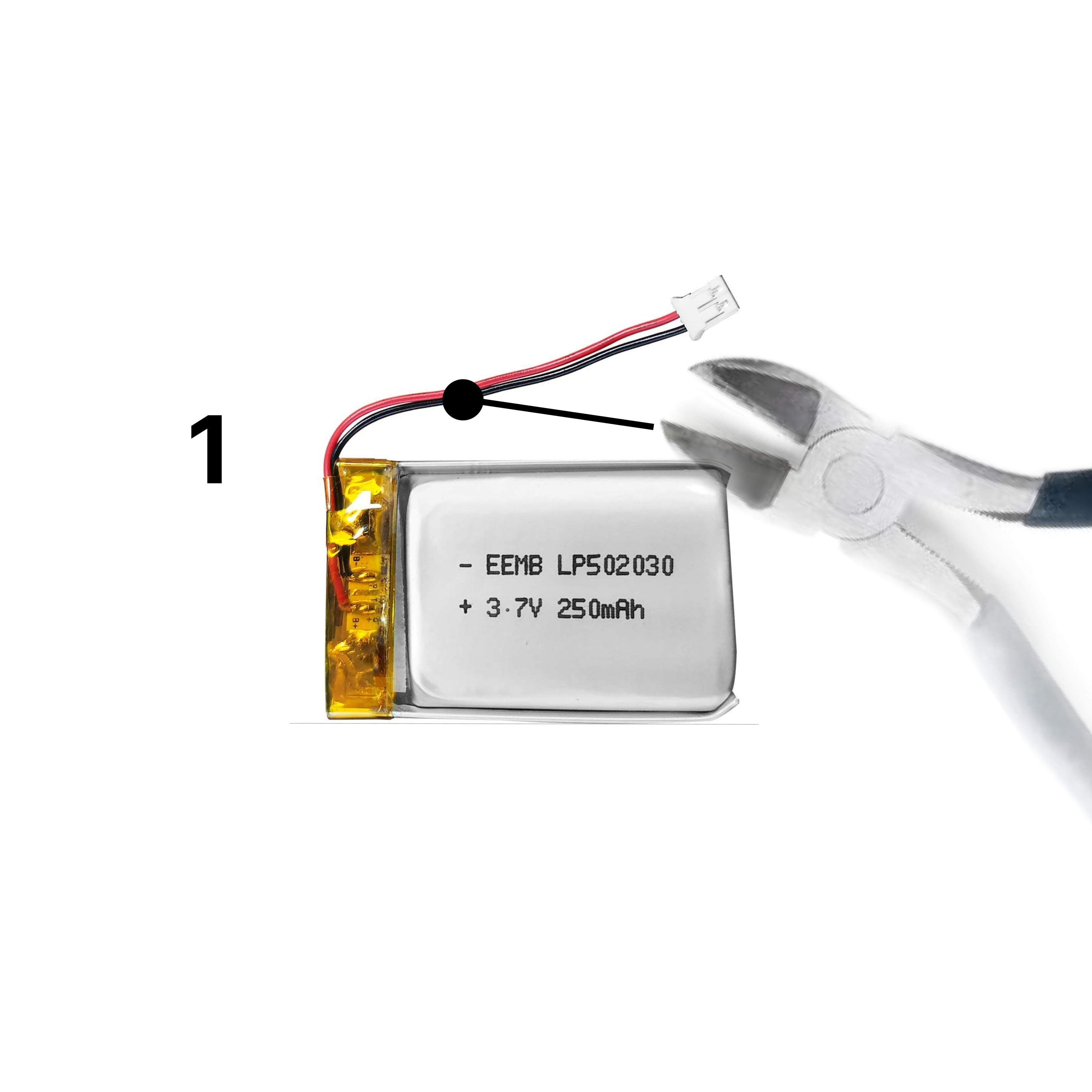 Remove a small portion of insulation from both ends of the cut wire using a wire stripper.
Use the **28 AWG** notch on your wire stripper for best results.
Remove a small portion of insulation from both ends of the cut wire using a wire stripper.
Use the **28 AWG** notch on your wire stripper for best results.
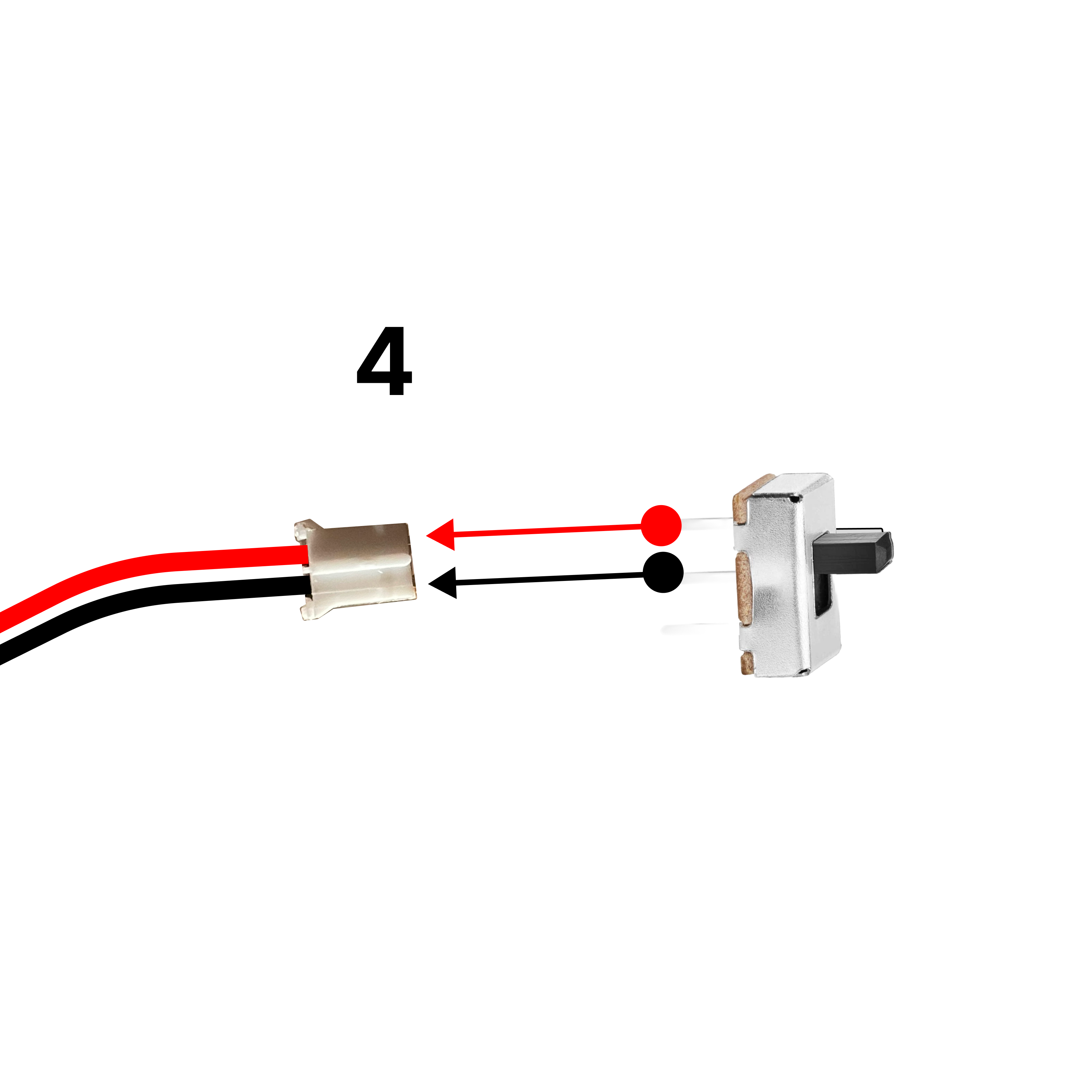
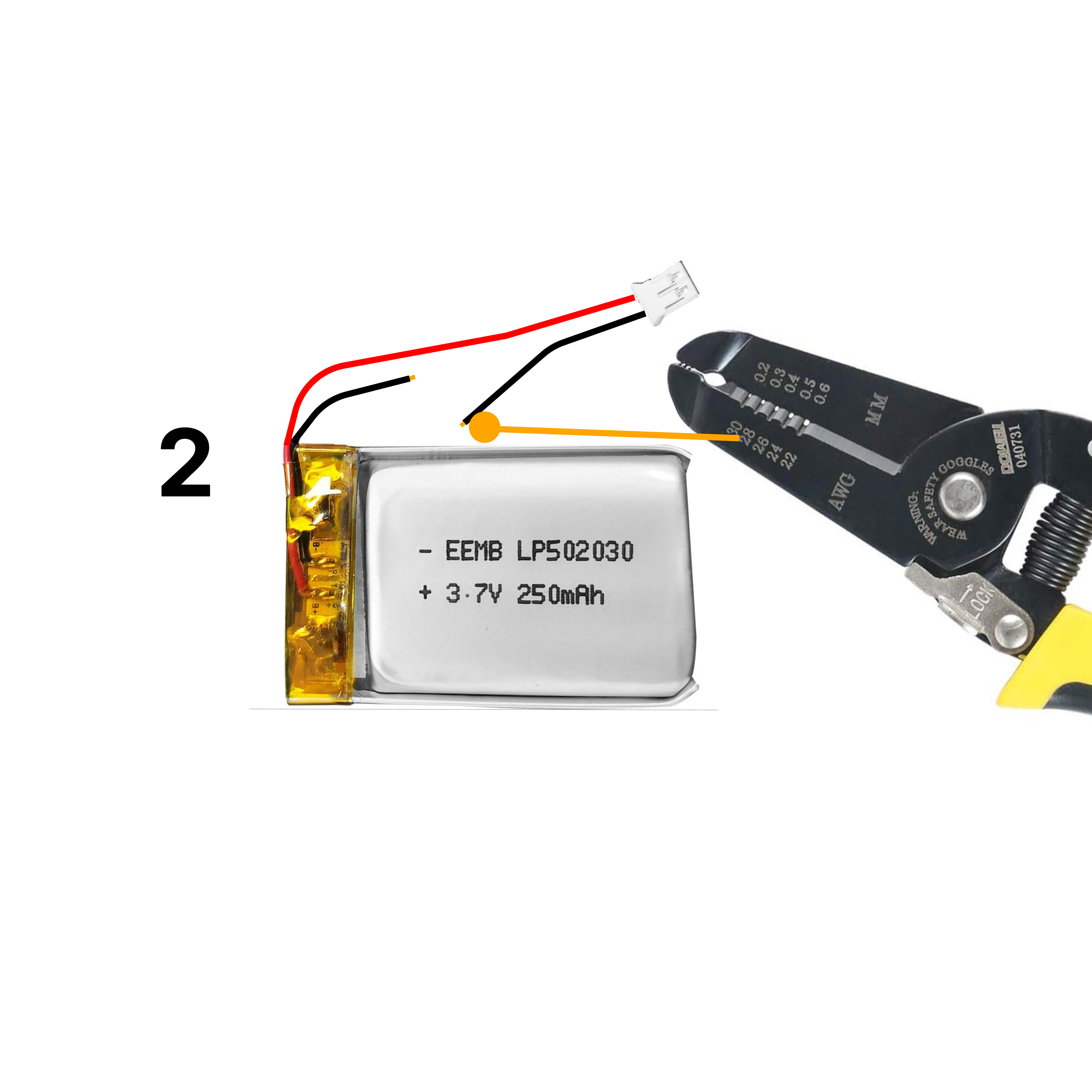 Follow the soldering diagram to connect the battery to the board. The switch goes in-line with the black (ground) wire.
 Be careful with soldering! Use proper ventilation and safety equipment.
Insert the switch securely into the battery connector circuit.
Be careful with soldering! Use proper ventilation and safety equipment.
Insert the switch securely into the battery connector circuit.
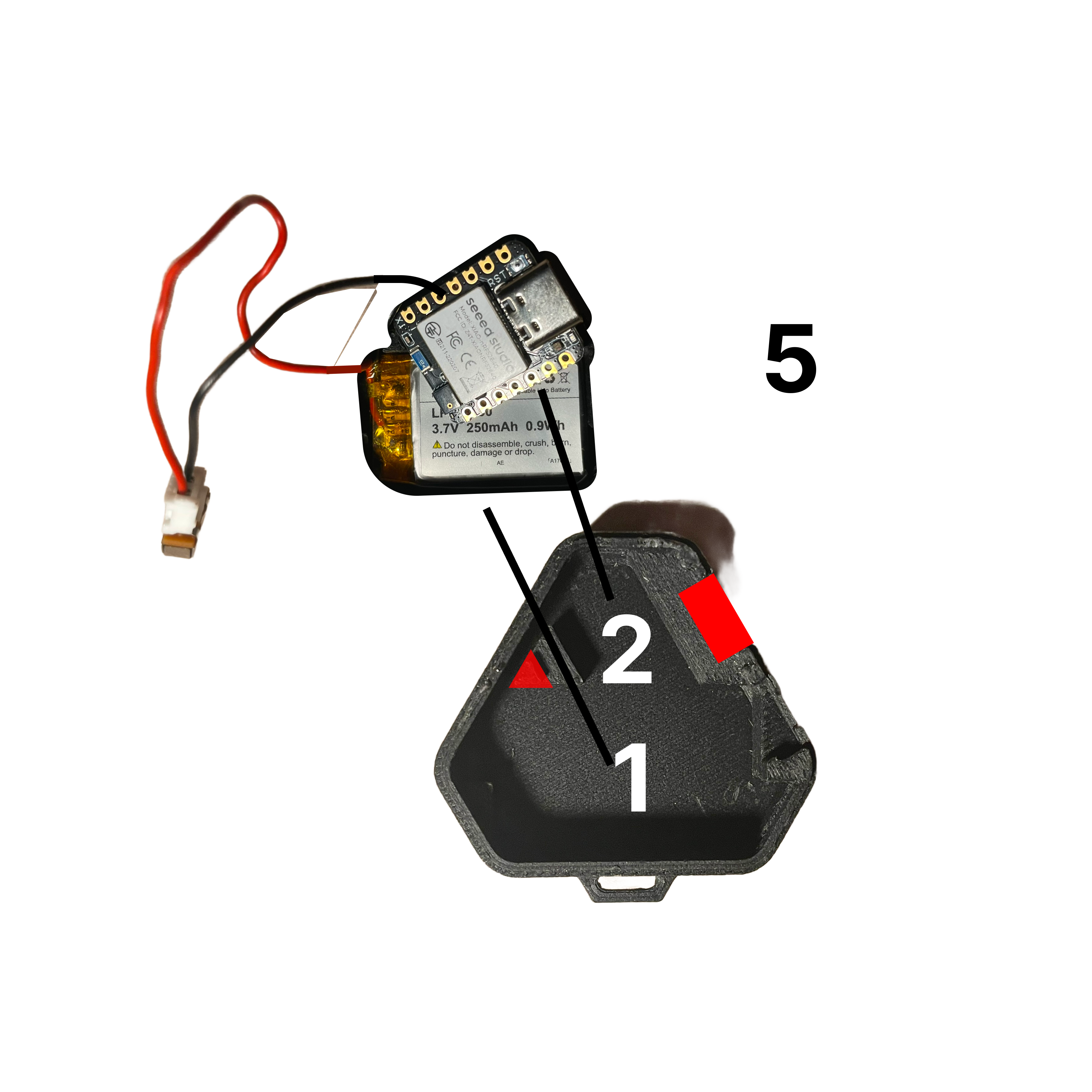
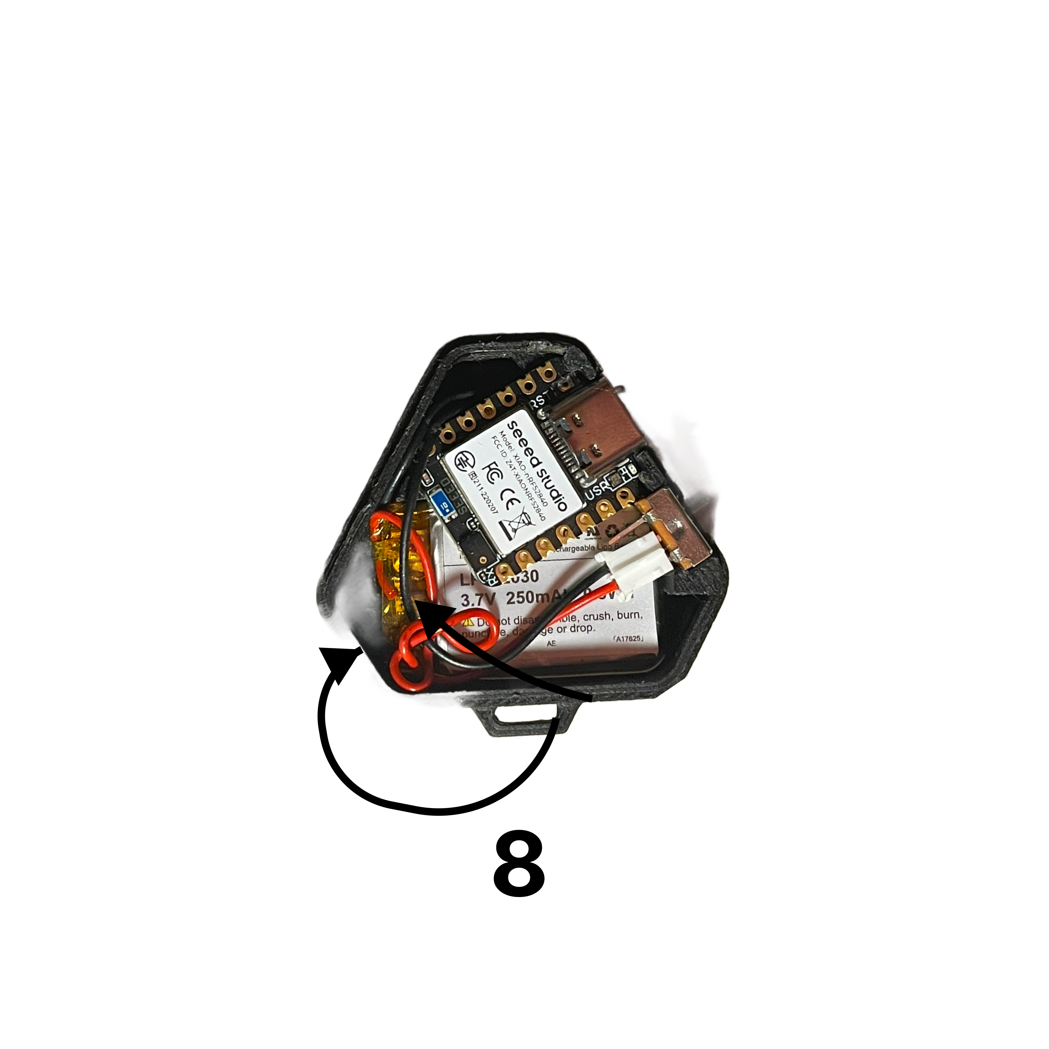
 Carefully place the battery and board into the 3D-printed case.
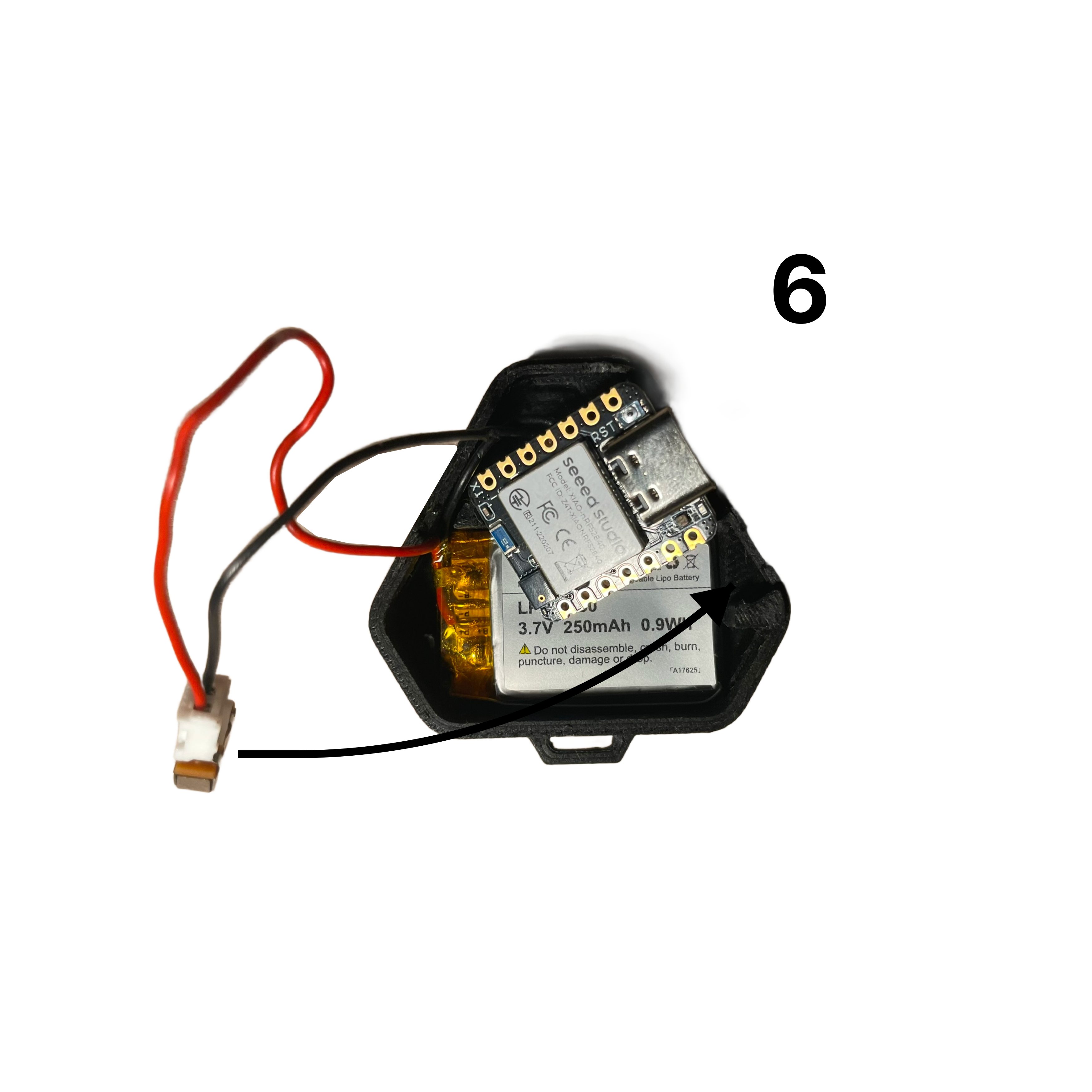
 Insert the switch into the notch next to the USB-C slot.
 Twist the longer red wire gently to help organize it within the case.
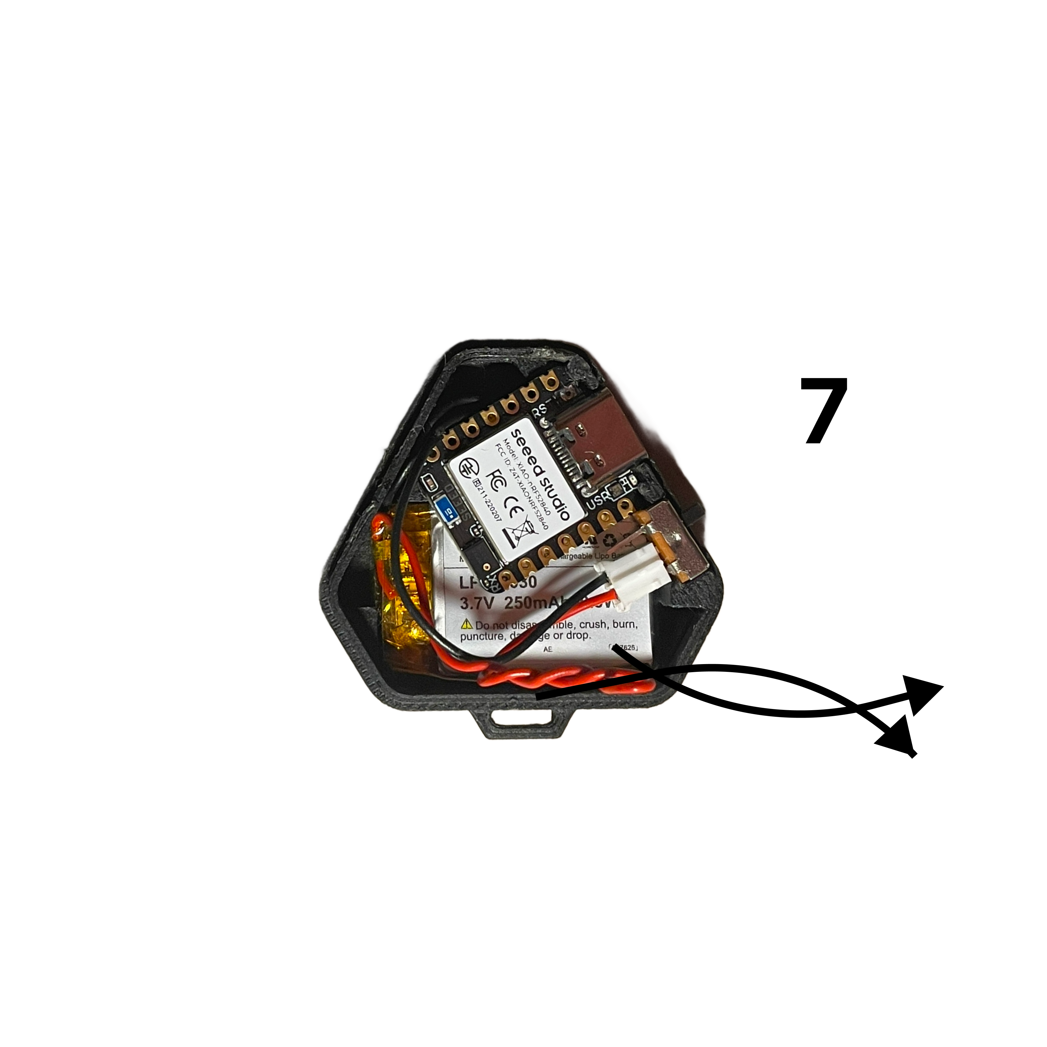 Carefully curl the twisted wire and place it to the side to ensure it fits within the case.
 Align the lid with the case using the ridges as a guide and snap it into place.
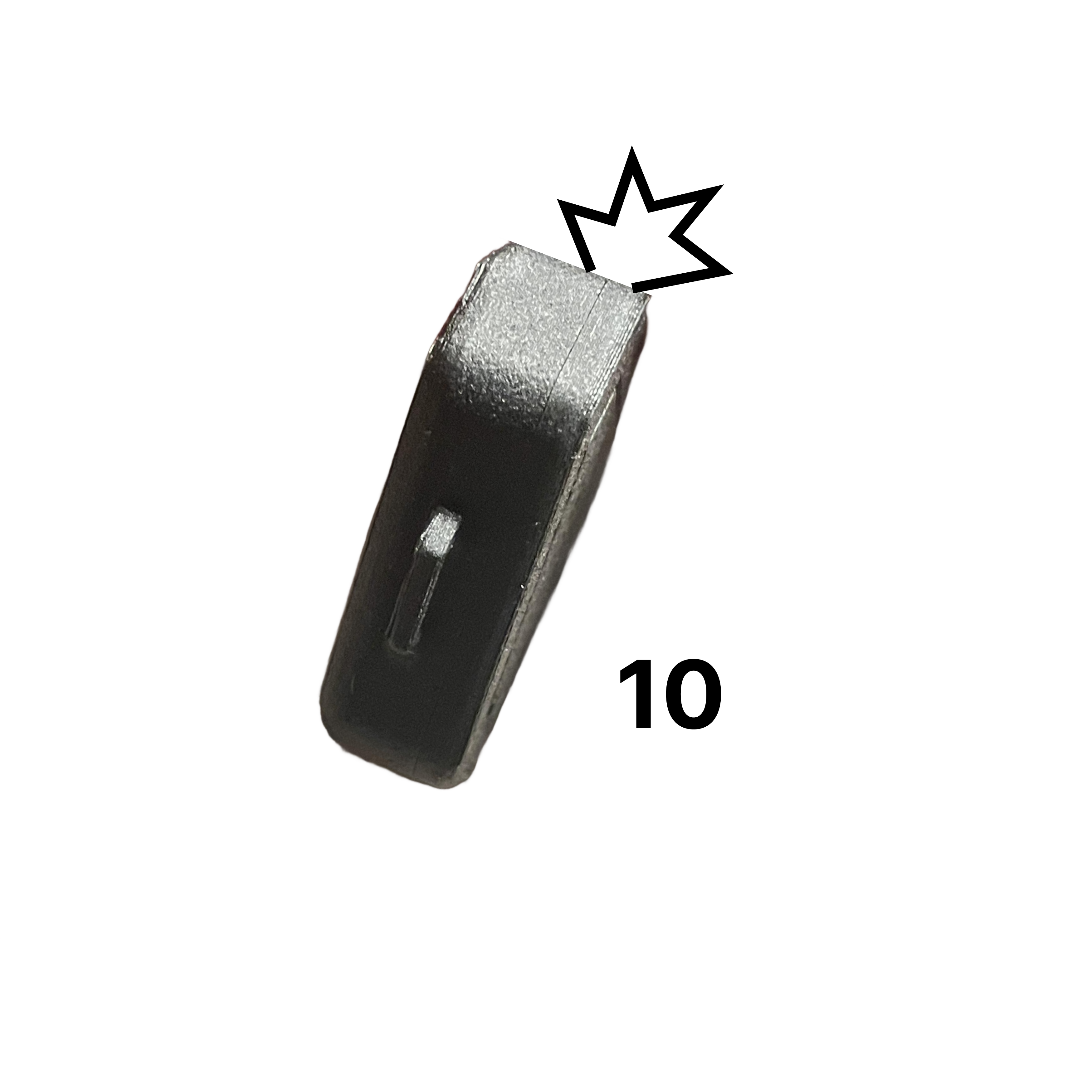
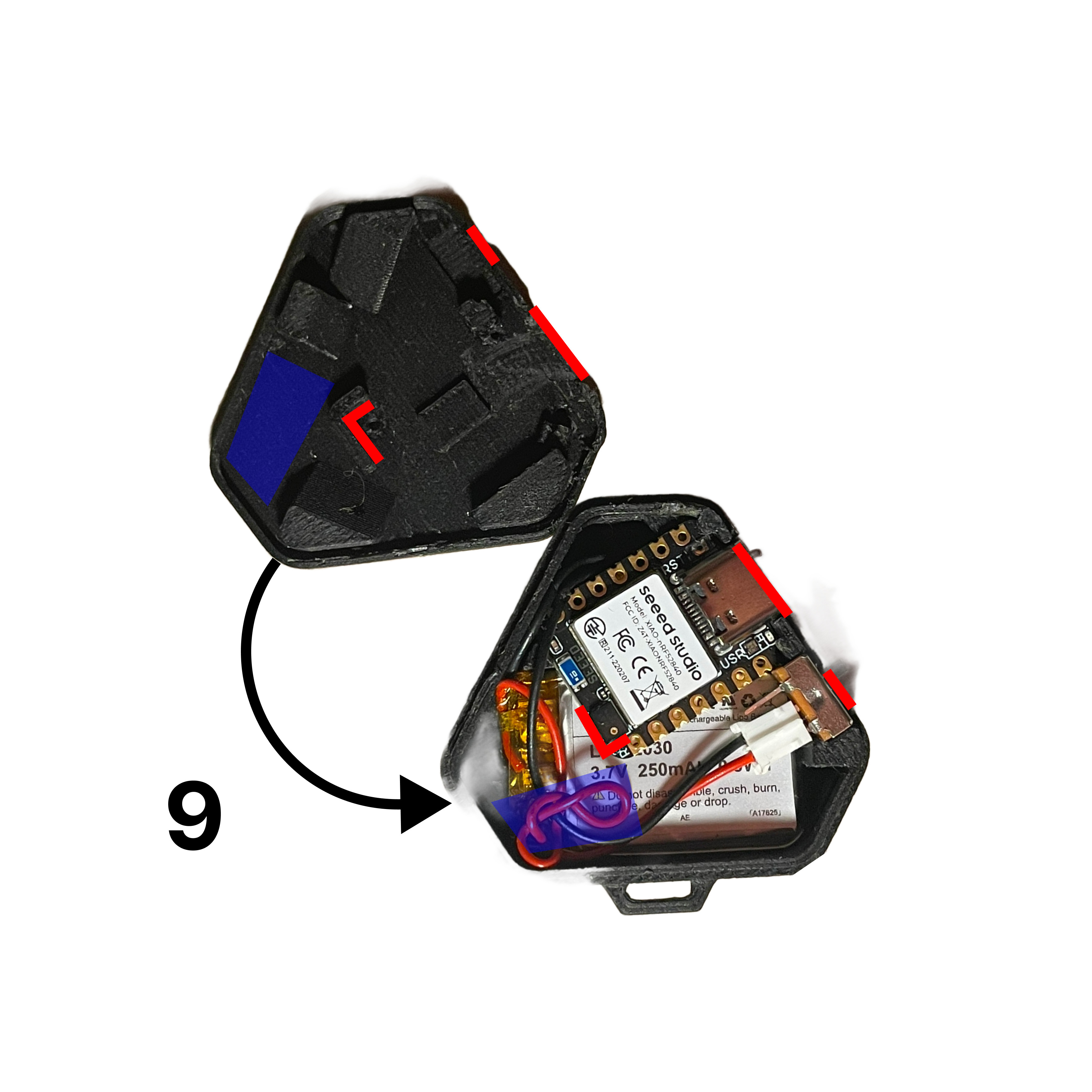 Apply even pressure around the edges to ensure the seams snap securely into place.
 ***
## Charging Instructions
**Important:** Omi can only charge when it is powered **ON**. The device will not charge if powered off.
* Use a standard USB-C cable to charge
* The LED will indicate charging status
* A full charge takes approximately 1-2 hours
***
## Congratulations!
You now have a fully assembled Omi device!
Install the latest firmware on your device
Download and configure the Omi app
Having issues? Get help from our community or contact support
Get help from the community on Discord
***
## Charging Instructions
**Important:** Omi can only charge when it is powered **ON**. The device will not charge if powered off.
* Use a standard USB-C cable to charge
* The LED will indicate charging status
* A full charge takes approximately 1-2 hours
***
## Congratulations!
You now have a fully assembled Omi device!
Install the latest firmware on your device
Download and configure the Omi app
Having issues? Get help from our community or contact support
Get help from the community on Discord