Bill of Materials
The BOM contains 88 components across the mainboard, charger board, FPC, and mechanical assembly. Download:Key Components
Passive Components
The mainboard uses 0201-size passives (resistors, capacitors) primarily from YAGEO and Murata. See the full BOM CSV for complete listings including designators.Assembly Reference
Exploded View
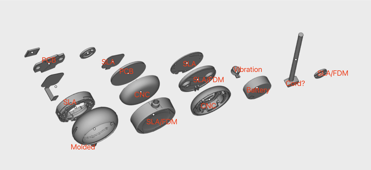
- Front aluminium cover (CNC machined)
- LED light guide (SLA/translucent)
- Main frame (SLA/translucent PC+ABS)
- PCB mainboard with microphones, SoC, flash
- FPC connecting to charging contacts
- Battery (150mAh LiPo)
- Vibration motor
- Silicone pad
- Back aluminium cover (CNC machined)
Build Guide
- Core Assembly
- Packaging & QA
1
Prepare workspace
2
Install PCB into frame
Place the mainboard PCB into the SLA frame on the mounting posts. Board should sit flat with no rocking. Connect the FPC cable to the board-to-board connector.
3
Connect battery and motor
Plug in the 150mAh LiPo battery. Route the cable to avoid pinching. Attach the vibration motor with double-sided tape.
4
Install magnets and silicone pad
Apply UV adhesive to magnet seats. Insert 4x N52 magnets (D3×H3mm). Cure with UV lamp for 30 seconds each.Place the silicone pad over the battery/motor assembly.
5
Close enclosure
Attach aluminium covers (Case A front, Case B back). Secure with 3x Phillips screws (CM1.2×5). Apply S300 glue around the seam.
Before sealing: test charging contact continuity, verify BLE advertising, confirm both mics record audio.
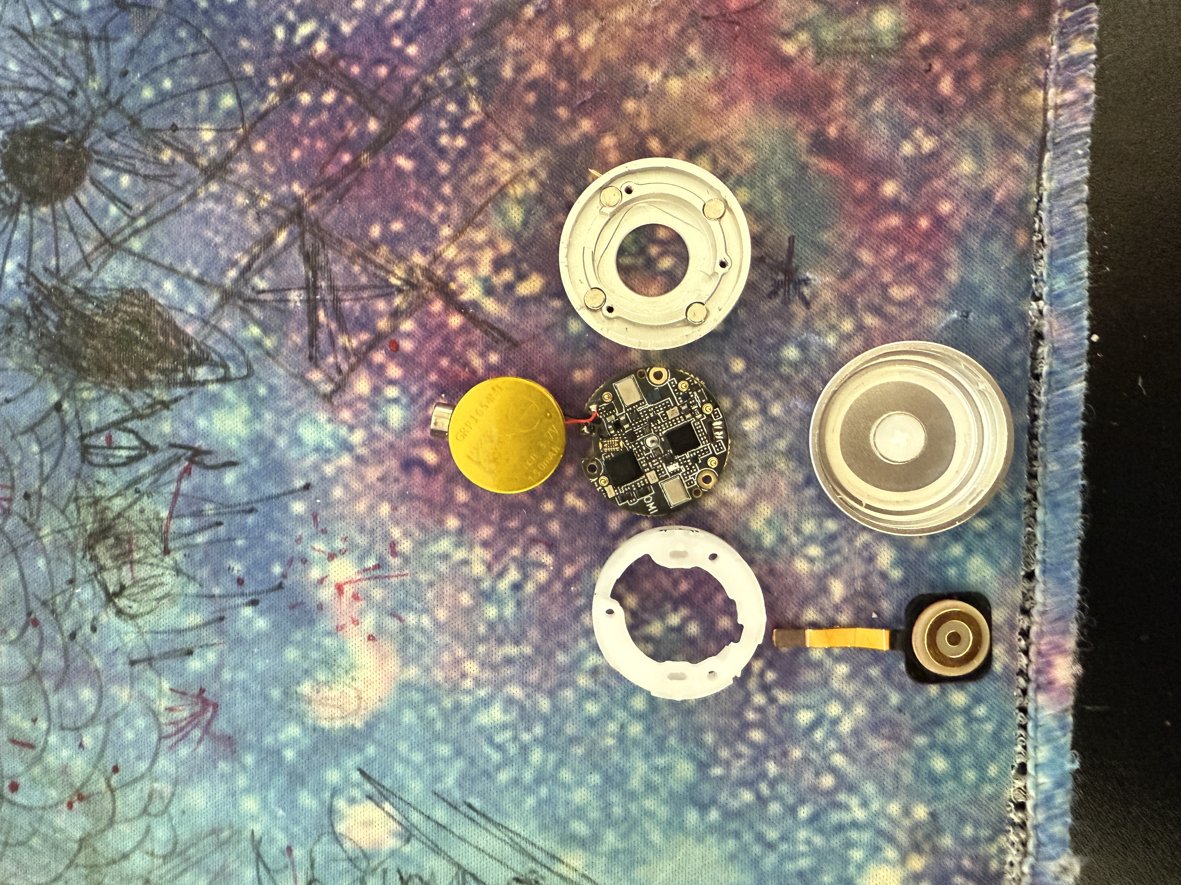
Reference Photos
Assembly photos are inassembly/photos/:
materials-labelled-exploded-view.jpg— All components identifiedmaterials-labelled.jpg— Materials and finish calloutscomponents-disassembled.jpg— Individual components laid outouter-aluminium-covers.jpg— CNC aluminium cover detail
Additional Mechanical Parts
File Integrity
All design files include SHA-256 checksums for verification against the original source files.View Checksums
SHA-256 checksums for all 58 design files (ZIP, STEP, PDF, BOM, images)